How Crosstalk Can Impact Umbilical Electrical Integrity Monitoring
October 21, 2021
Most electrical engineers will know what crosstalk is. However, the various effects of crosstalk in long cables such as subsea umbilicals are not always recognised. Therefore, crosstalk itself is not always identified as the root-cause of operational problems. Before we look at the impact of crosstalk, let’s relook at some of the basic concepts of crosstalk and what it is.
If you look up ‘crosstalk’ in an English dictionary, you will find a definition that reads something like ‘unwanted signals in one channel of a communications system as a result of a transfer of energy from one or more other channels’. The dictionary will also inform you that the use of the word was first recorded around 1885-90.
Early meaning and use of the term ‘crosstalk’ was more related to interference heard on a telephone or radio. Those of us old enough to have used analogue telephones would have regularly heard strange conversations on the line when crosstalk was the sinister cause of being able to listen in to other peoples’ conversations. Therefore, it is not surprising that the initial use of ‘crosstalk’ occurred not long after Alexander Graham Bell’s first telephone call in 1876.
From Maxwell’s equations, we know that electric currents in a conductor create electric and magnetic fields, and so electric signals in different conductors create their own fields and where these fields overlap, they interfere with each other’s signals. For example, if two wires next to each other carry different signals, the currents in them will create magnetic fields that will induce a smaller signal in the neighbouring wire. Cable designs try and eliminate cross-channel interference through the use of screened twisted pairs. The twisting of a pair of wires that carry the same current in opposite directions (as is normally the case) means that the net field resulting from the two wires is zero. The metal screen also has the effect of significantly attenuating any residual electric field.
This twisting and screening is common practice in signal channels but not with power channels where the conductors are designed for high currents, and crosstalk interference does not affect the purpose or efficiency of the power channel.
For surface to subsea communications systems, the electrical system analysis undertaken by the Control System Vendor always ensures that the communications system will operate with certain levels of crosstalk present but, in any case, the use of digital rather than analogue communications means that the signals are less susceptible to crosstalk interference.
So generally, the cable design and use of digital communications means that subsea umbilical problems with crosstalk should not be anticipated. However, that is not the full story: in electrical circuits sharing a common signal return path, electrical impedance in the return path creates common impedance coupling between the signals. In this case, the crosstalk is therefore usually caused by undesired capacitive, inductive, or conductive coupling from one circuit or channel to another.

Up to 254 V-LIM units can be synchronised simultaneously using a switch/router.
Most subsea umbilicals utilise Insulation Monitoring Devices (IMDs) to detect any degradation in the insulation material surrounding the power conductors. IMDs from different manufacturers operate in slightly different ways but fundamentally, they all apply a signal between the copper conductors and ground (i.e. using the sea water and ground as the return path). If an umbilical carries more than one power pair, which is the norm, then there would typically be an IMD monitoring each power pair separately. However, each IMD will use the same ‘earth’ return path. The signal that the IMD applies between the conductor pair and ground is used to measure the leakage current that is flowing through the insulation material. Ideally, this current should be negligible in magnitude, but will increase as the insulation degrades. In order to fully characterise the cable integrity, the IMD should interpret the current flowing to provide both a resistive and capacitive component measurement (insulation resistance and insulation capacitance).
In multi-channel umbilicals utilising more than one IMD, the multiple IMD voltage sources and common return path means that any inductive and capacitive coupling between channels can result in complex and varying return path currents. Since each IMD is effectively measuring the return path current, the consequence of this coupling or ‘crosstalk’ means that the reported Insulation Resistance or Insulation Capacitance from each IMD will likely be unstable (varying in value) or will simply read too high or too low. The consequence is that the IMD readings will not be accurate and will erroneously report incorrect measurements.
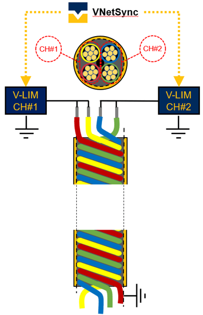
The problem is exacerbated if two power pairs (channels) co-exist as a ‘quad’ within the umbilical and also if the umbilical is long. The closer the proximity of the power pairs and the longer that the pairs run together (length) the worse the capacitive and inductive coupling will be and therefore the worse the crosstalk.
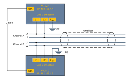
The IMD supplied by Viper Innovations, the V-LIM, has been designed specifically for the subsea applications and umbilicals; it is optimised to measure accurately over a wide range of insulation resistance values, can accommodate the high capacitances of long umbilicals, and in respect of the crosstalk issues discussed in this article, can incorporate an ethernet interconnect between all V-LIMs connected to any one umbilical. This ethernet connection provides precise measurement synchronisation for each V-LIM, ensuring that the V-LIM hardware and software completely eliminates the effects of any crosstalk.
The result of this synchronisation means that the electrical integrity of each power channel can be measured, providing stable and accurate data completely unaffected by any adjacent V-LIM. As a result of the exceptional results obtained, Viper have been busy replacing legacy IMD systems across the world where operators have been reluctantly living with highly inaccurate and varying readings. The synchronisation is bespoke to the V-LIM and so any upgrade that requires the synchronisation function will require all IMDs to be replaced with V-LIMs.


