View this film to find out why insulation resistance (IR) is important to the operation of your subsea electrical system.
WHAT IS IR?.
Every electric wire is covered with some form of electrical insulation, whereas the wire itself is usually copper, which is a good conductor of the electric current that powers the equipment. The insulation must be just the opposite from a conductor: it should resist current and keep the current in its path along the conductor. Note, however, that no insulation is perfect so some electricity does flow through the insulation to ground.
‘Good’ insulation means a relatively high resistance to current and also the ability to maintain that high resistance over time. So, measuring insulation resistance (typically referred to as ‘IR’) regularly could indicate how “good” the insulation is and can also check trends toward its deterioration.
While regulations vary throughout the world, the facts about the deterioration of cables, especially those located on the seabed, do not. The physics remain the same. Any electrical insulation will begin to deteriorate after it is made. The environment in which the subsea cable lies, however, is particularly harsh and the conditions will almost certainly increase the rate of deterioration. If the subsea cable insulation becomes compromised it increases the risks of equipment failure (and so lost production).
WHY IS IT IMPORTANT?.
Insulation resistance needs to be maintained at safe levels to not only shield against loss of production but also to protect against electric shocks to humans.
When your cables, connectors and umbilicals are new, the electrical insulation should be in excellent condition. Nevertheless, insulation is subject to many effects which can cause it to fail – electrical stresses, mechanical damage, moisture or general ageing. As pinholes or cracks develop, water will penetrate the surfaces of the insulation, providing a low resistance path for leakage current.
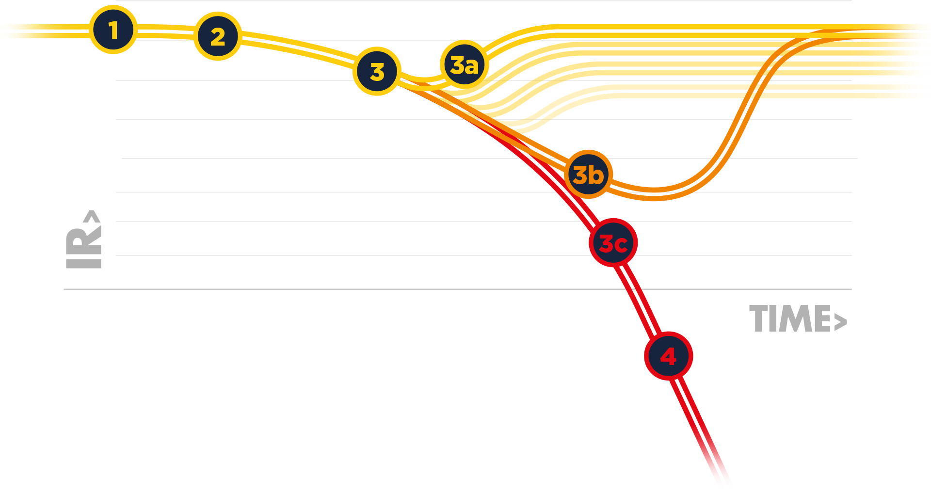
Sometimes the drop in insulation resistance is sudden, but usually, it drops gradually, giving plenty of warning, if checked periodically. Good insulation has high resistance; poor insulation, relatively low resistance, but what really matters is the trend in readings over a time period, showing lessening resistance and warning of impending problems.
HOW IS IT MONITORED?.
IR is typically monitored using a Line Isolation Monitor (LIM) or an Insulation Monitoring Device (IMD). Primarily the LIM is a safety device to prevent exposure of personnel to electrical hazards resulting from a deterioration of the insulation resistance. It also provides a status of the electrical insulation integrity which can be used to help determine the life expectancy of the system.
For subsea cables, the traditional cost of maintenance and repair is extremely high. Continuous monitoring helps to provide a clearer picture of trends in insulation resistance so operators can make better strategic decisions.
Floating earth systems (known as IT or Isolation Terra) are commonly used as they promote the high availability of the system – a vital consideration for subsea networks. Such systems continue to work even if there is a single fault to ground. Although systems still operate and production can continue, a second insulation fault can result in dangerously high leakage currents that could present a high risk of an electric shock on human contact. A second earth fault can also lead to an accelerated failure of the electrical system through the erosion of the copper conductors as a result of current leakage and the electrochemical reaction of the copper in the seawater.
WHY DO I NEED ONE?.
The integrity of subsea power and signal channels are important to the long-term operation of the Production Control System. This integrity is predominantly determined by the insulation properties of a cable, where the insulation acts as the barrier between two live conductors and between the live conductors and the surrounding seawater.
Fundamentally, it is the integrity of the insulation material that prevents a potentially fatal risk to personnel from leakage currents and also maintains the delivery of the electrical power and communications that are needed to maintain the hydrocarbon production.
Current through and along insulation is made up partly of a relatively steady current in leakage paths over the insulation surface. Electricity also flows through the volume of the insulation. The total leakage current comprises three components:
Capacitance Charging Current: Current that starts out high and drops after the insulation has been charged to full voltage.
Absorption Current: Also an initially high current which then drops (for reasons discussed under the section Time-Resistance Method).
Conduction or Leakage Current: A small essentially steady current both through and over the insulation.
HOW DOES A LIM WORK?.
In Alternating Current (AC) IT systems, the measured leakage current depends only on line-to-ground insulation parameters of single conductors and not of the wire-to-wire insulation.
A device that is used for monitoring leakage current and therefore, indirectly, the insulation resistance is commonly known as a Line Insulation Monitor (LIM) or an Insulation Monitoring Device (IMD). From here on we will just use the LIM terminology. A LIM can use a range of measurement techniques to find the leakage current and detect the magnitude of the failure in the insulation. The leakage current is measured by applying a fixed DC (Direct Current) voltage, a low-frequency AC voltage, a combination of the two, or a series of positive and negative going square-wave pulses. The leakage current that results from this applied measurement signal can be converted into an impedance to ground (impedance being the opposition of electrical current flow in an AC circuit). Depending on the capability of the LIM, the output measurement will either be just the leakage resistance (insulation resistance) or it could also include the leakage capacitance – as per the capacitive charging current.
If the measured impedance decreases below a predetermined value, due to a first fault to ground, a local and a remotely enunciated alarm will be initiated.
INTRODUCING V-LIM.
Download the V-LIM Datasheet.


